Neural Network Energy Control
of Combustion Engines for Automotive
Software Applications
Marcos Henrique Carvalho Silva
https://orcid.org/0000-0002-1318-086X
Universidade de São Paulo, Brazil
André Vinícius Oliveira Maggio
https://orcid.org/0000-0002-9331-5663
Universidade de São Paulo, Brazil
Armando Antônio Maria Laganá
https://orcid.org/0000-0002-0085-1927
Universidade de São Paulo, Brazil
João Francisco Justo Filho
https://orcid.org/0000-0003-1948-7835
Universidade de São Paulo, Brazil
Bruno Silva Pereira
https://orcid.org/0009-0000-3943-2132
Universidade de São Paulo, Brazil
Demerson Moscardini
https://orcid.org/0009-0005-1999-6121
Universidade de São Paulo, Brazil
Received: July 08, 2023 / Accepted: September 09, 2023
doi: https://doi.org/10.26439/ciis2023.7083
ABSTRACT. This article focuses on the application of neural network control for energy generation in an internal combustion engine. A two-layer neural network architecture was developed and tested using laboratory data obtained from a bench dynamometer to accurately identify the network’s parameters. The neural network is employed to establish an accurate correlation between the magnitude of actuation signals and the fundamental variables responsible for regulating energy generation within the system. The control system utilizes a gain-scheduling routine to adjust the controller’s gain, which attenuates the increment for low error values. An energy generation model is presented to design a virtual engine, enabling accurate control strategies. To ensure the safe operation of the engine, a safety routine is implemented to prevent the control action from assuming values that could negatively impact the vehicle’s response to the driver’s commands. The developed controller demonstrates a low average absolute error in steady-state conditions and a low average rise and fall time during transient states, ensuring both drivability and good engine performance. To enable the application in software, in structures such as hardware-in-the-loop simulation and engine control units, systems are implemented to ensure real-time operations.
KEYWORDS: neural network control / energy generation / software development
Control energético de motores de combustión mediante redes neuronales para aplicaciones de software de automoción
RESUMEN. Este artículo se enfoca en la aplicación del control mediante redes neuronales para la generación de energía en un motor de combustión interna. Se desarrolló una arquitectura de red neuronal de dos capas y se la probó utilizando datos de laboratorio obtenidos de un dinamómetro de banco para identificar con precisión los parámetros de la red. Esta se utiliza para establecer una correlación precisa entre la magnitud de las señales de actuación y las variables fundamentales responsables de regular la generación de energía dentro del sistema. El sistema de control implementa una rutina de programación de ganancia para ajustar la ganancia del controlador, lo que disminuye el incremento para valores de error bajos. Se presenta un modelo de generación de energía que permite diseñar un motor virtual, lo cual facilita el desarrollo de estrategias de control precisas. Para garantizar el funcionamiento seguro del motor, se implementa una rutina de seguridad que previene que la acción de control adquiera valores que podrían tener un impacto negativo en la respuesta del vehículo a las instrucciones del conductor. El controlador desarrollado demuestra un bajo error absoluto promedio en condiciones de estado estable y un bajo tiempo promedio de subida y caída durante estados transitorios, asegurando la capacidad de conducción y el buen rendimiento del motor. Para habilitar la aplicación en software, en estructuras como el hardware-in-the-loop y la unidad de control del motor, se implementan sistemas para garantizar la operación en tiempo real.
PALABRAS CLAVE: control mediante redes neuronales, generación de energía, desarrollo de software.
1. Introduction
The relentless pursuit of improvements in engine performance is one of the main objectives of the automotive industry (Pandey et al., 2021). As drivers become increasingly demanding with regard to vehicle drivability, it is essential to apply advancements in the field of control to meet these demands. Technological advancements have driven significant improvements in automotive engine performance. Through the development of more efficient controls, it is possible to optimize engine performance and ensure a more satisfying driving experience for drivers. One key factor in this context is precise engine control, which positively impacts its performance. Advanced controls enable accurate tracking of the desired reference, resulting in improved drivability. When the engine responds promptly and accurately to driver commands, the driving experience becomes smoother and safer (Wang et al., 2020).
The use of neural networks in control has proven to be of great importance in and impact on various fields of application. Neural networks, which are computational models inspired by the functioning of the human brain, have the ability to learn and adapt from input data. When applied to control, neural networks can learn complex and nonlinear patterns, allowing for more precise actions (Shahbaz & Amin, 2023). This is especially relevant in nonlinear systems. By utilizing neural networks in control, it is possible to achieve a higher level of efficiency, precision and adaptability, which contributes to optimizing processes, reducing errors and promoting significant technological advancements (Ineza Havugimana et al., 2023).
There are notable research studies in the field of control with neural networks for internal combustion engines. Moriyasu et al. (2019) controlled the engine’s air system using a neural network-based controller and an unscented Kalman filter. Zhao et al. (2020) controlled the engine speed using a radial basis function-based proportional integral derivative (PID) controller based on neural network theory. Wong et al. (2020) developed an extreme learning machine (ELM)-based adaptive neural control algorithm to control the idle speed of the engine. Gordon et al. (2022), aiming to control combustion for improved pollutant emission levels, used a deep neural network (DNN) to develop a predictive controller. Vignesh & Ashok (2021) used a DNN to create a predictive model in order to develop optimal injection control for emission reduction.
2. Methodology
A mean-value model is used for energy generation. In order to estimate the effective torque value 𝑇𝑒, it is considered that the effective torque can be obtained by subtracting the pumping losses 𝑇𝑝𝑢𝑚𝑝 and friction losses 𝑇𝑓𝑟𝑖𝑐 from the indicated torque 𝑇𝑖, as described by equation (1).
𝑇𝑒 = 𝑇𝑖 − 𝑇𝑝𝑢𝑚𝑝 − 𝑇𝑓𝑟𝑖𝑐. (1)
The estimation of the indicated torque depends on several factors, such as the engine speed, intake manifold pressure, air-fuel ratio, admitted fuel flow and ignition timing. In equation (2), the effects of the air-fuel ratio, ignition timing and load are separated into three factors, respectively 𝑒𝜆, 𝑒𝜉 and 𝑒𝛼 (Guzzella & Onder, 2010). These factors relate the indicated torque 𝑇𝑖 to the torque 𝑇𝑓 that would be produced if the thermal efficiency of the engine were unity. The optimum indicated efficiency is achieved with the optimal ignition timing and air-fuel ratio values. Under these conditions, the indicated efficiency is represented by the factor 𝑒𝛼 itself.
𝑇𝑖 = 𝑒𝛼. 𝑒𝜆. 𝑒𝜉. 𝑇𝑓 (2)
The relationship between the indicated torque and the ignition timing is parabolic (Moskwa, 1988). When the ignition angle 𝜉 is set to the maximum brake torque (MBT) angle 𝜉0, it is considered that there are no losses in efficiency due to the timing of ignition. The maximum brake torque angle is the angular position of the spark discharge that provides the highest indicated efficiency. The opening of the parabola is directly related to the coefficient 𝑘𝜉, as shown in equation (3). The factor that accounts for the efficiency losses due to the air-fuel ratio values can be approximated by equation (4) (Eriksson & Nielsen, 2014). The factor 𝑒𝛼 is mapped based on the engine speed and intake pressure.
𝑒𝜉 = 1 − 𝑘𝜉. (𝜉 − 𝜉0)2 (3)
𝜆 𝑓𝑜𝑟 𝑟𝑖𝑐ℎ 𝑚𝑖𝑥𝑡𝑢𝑟𝑒𝑠 (4)
𝑒𝜆 = { 1 𝑓𝑜𝑟 𝑝𝑜𝑜𝑟 𝑚𝑖𝑥𝑡𝑢𝑟𝑒𝑠
A multivariable neural network controller is employed to control the useful energy generation of the engine through the following actuators: throttle valve, fuel injector and ignition coil. The neural network is trained using data obtained in the laboratory. During training, values such as throttle opening, ignition angle, injection timing, oil temperature, engine speed, intake pressure, air-fuel ratio and effective torque are provided to design a neural network controller that provides appropriate values for throttle opening, ignition angle and injection timing for a desired effective torque. Current and delayed values of intake pressure and air-fuel ratio signals are used, aiming to enhance the predictive capability of the neural network. There is a set of phenomena that occur, such that changes in air intake or fuel injection gradually impact on the air-fuel ratio.
The neural network controller operates in parallel with a gain-schedule routine, which adjusts the controller’s gain increment by attenuating it when the error magnitude between the reference and effective torque is small. The developed controller is validated in a simulation with the modeled engine, as shown in Figure 1. The virtual engine is connected to a gain-scheduling routine, a neural network control system and a safety interface. The safety interface ensures that the control signals received by the actuators do not have values that could compromise the drivability and safety of the engine.
For applicability in automotive software, all systems must exert low processing demand in order to enable their real-time implementation. In this way, systems can be programmed in a hardware-in-the-loop environment or in the electronic control unit due to their capability to operate in real-time (Schäuffele & Zurawka, 2016).
Figure 1
Simplified diagram of the control system with the engine model

3. Experimental Setup
In order to acquire experimental data for the purpose of engine modeling, a laboratory environment equipped with a bench dynamometer and an external cooling system, as depicted in Figure 2, was employed. The engine under study was the EA-111 VHT 1.6 l, which possesses several features, including indirect port injection, fuel compatibility with both gasoline and ethanol, absence of gas recirculation, spark ignition, eight valves, naturally aspirated configuration and a compression ratio of 12.1.
Figure 2
EA-111 VHT 1.6 l engine coupled to the dynamometer

4. Results and Discussion
Initially, data acquisition is performed to determine multiple engine parameters. Gas pumping losses correspond to the reduction in torque resulting from the energy expended in transferring gas from a low-pressure location (intake manifold) to a high-pressure location (exhaust manifold). These losses can be quantified and computed based on the engine speed and intake pressure. By calculating the pumping loss at various operating points, the map illustrated in Figure 3 is generated. For specific insights into this calculation methodology, refer to Guzzella and Onder (2010).
Figure 3
Pumping torque map

There are various methods to estimate torque losses due to friction. In this research, an active bench dynamometer capable of rotating the engine while it is off was used. The force necessary to rotate the engine can be regarded as the force required to overcome friction. Consequently, the torque measured by the active dynamometer in this scenario, known as motored torque, provides an approximation of the friction values 𝑇𝑓𝑟𝑖𝑐. Motored torque values were obtained at different oil temperatures and engine speeds, as shown in Figure 4.
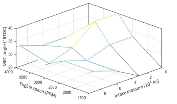
In order to construct the torque estimator, the optimal ignition angle and the optimal indicated efficiency were identified for various operating conditions. Figure 5 presents the results of the identification of the optimal ignition angle 𝜉0, while Figure 6 displays the results of the optimal indicated efficiency 𝑒𝛼.
Figure 4
Motored torque map
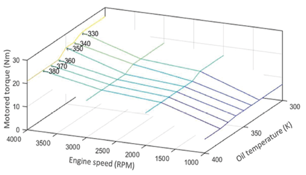
Figure 5
MBT angle map
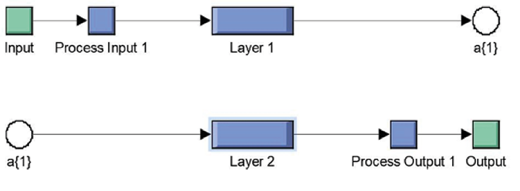
The comprehensive system diagram is depicted in Figure 7. The engine model encompasses various subsystems including the air intake system, the air-fuel mixture formation system and the energy generation system. To maintain drivability and driver safety, a safety module is incorporated to restrict control signals from assuming values that may compromise these aspects. The neural network control module comprises a two-layer neural network architecture as illustrated in Figure 8. Additionally, the gain-scheduling module generates signals to increment the control signals. However, this increment is attenuated for low absolute error values, considering the error as the discrepancy between the torque reference and the actual torque.
Figure 6
Indicated efficiency for optimal conditions
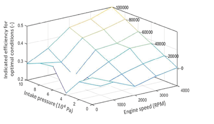
Figure 7
Simulink diagram of the control system with the engine model and the safety routine
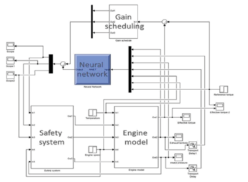
Figure 8
Two-layer neural network control
To validate the control design, simulations were conducted across a range of engine speeds. The simulation results for the engine operating at 2 000 RPM are presented in Figure 9, while Figure 10 showcases the outcomes for the engine at 3 000 RPM. Figure 11, additionally, displays the results obtained for the engine running at 4 000 RPM. In these figures, a comparison is made between the reference signal and the corresponding torque signal. To evaluate the control performance in both steady-state and transient regimes, step changes are applied to the reference signal.
Figure 9a
Torque reference (red signal) contrasting with torque signal (blue signal) in the simulink environment for 2000 RPM with negative step in the reference

Figure 9b
Torque reference (red signal) contrasting with torque signal (blue signal) in the simulink environment for 2000 RPM with positive step in the reference
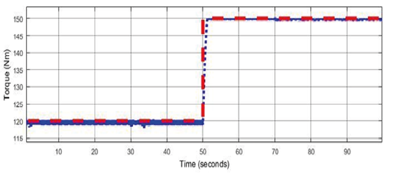
Figure 10a
Torque reference (red signal) contrasting with torque signal (blue signal) in the simulink environment for 3000 RPM with positive step in the reference

Figure 10b
Torque reference (red signal) contrasting with torque signal (blue signal) in the simulink environment for 3000 RPM with negative step in the reference

Figure 11a
Torque reference (red signal) contrasting with torque signal (blue signal) in the simulink environment for 4000 RPM with positive step in the reference

Figure 11b
Torque reference (red signal) contrasting with torque signal (blue signal) in the simulink environment for 4000 RPM with negative step in the reference

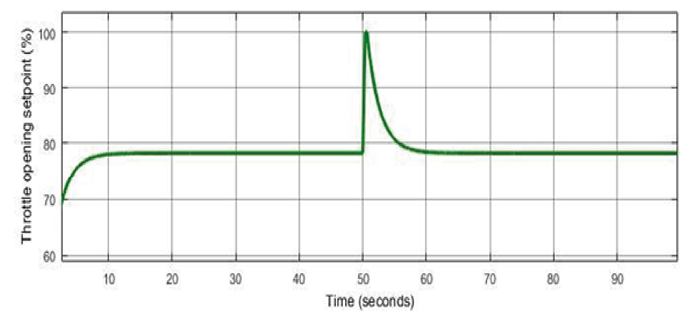
For a clearer understanding of the signal behavior in the transient regime, highlights of the simulation with the engine at 3 000 RPM are illustrated in Figure 12. The controller exhibited low values for both the rise and fall times in the transient regime and the mean absolute error in the steady-state regime across all engine speeds. For all engine speeds, the average absolute error values were less than 1 Newton meter, and the average rise and fall time values were less than 2 seconds. These results indicate that the developed controller demonstrates proper reference tracking, implying good drivability and safety for the driver. In order to assess the control effort, the control signals are depicted in Figure 13. The examination reveals that the control signal values are appropriate for each actuator, as they are within the range of executable values.
A comprehensive system simulation, encompassing a timeframe of 10 000 seconds, completed its execution within a mere 70 seconds on a standard computing device. This significant result validates the system’s viability for diverse automotive software applications, as it demonstrates real-time responsiveness, meeting the stringent requirements of such domains.
Figure 12a
Transient regime details in the application of a positive step in torque reference with the engine at 3000 RPM

Figure 12b
Transient regime details in the application of a negative step in torque reference with the engine at 3000 RPM
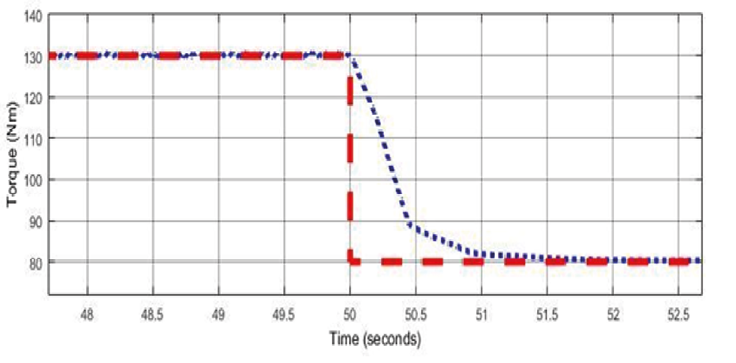
Figure 13a
Ignition angle control signal, in degrees before top dead center (° BTDC), for the engine
at 3000 RPM

Figure 13b
Injection timing control signal, in milliseconds, for the engine at 3000 RPM

Figure 13c
Throttle opening setpoint control signal, in opening percentage, for the engine at 3000 RPM
5. Conclusions
This article presented the application of a two-layer neural network for controlling energy generation in an internal combustion engine. The identification of the neural network parameters was performed using laboratory data obtained with a bench dynamometer, establishing a relationship between the main variables responsible for energy generation. Additionally, a gain-scheduling routine was implemented to adjust the controller gain, attenuating the control action increment for low error values.
To ensure the safety and proper response of the vehicle to driver commands, a safety routine was developed to prevent the control action from reaching undesired values. The experimental results obtained with the developed controller demonstrated a low value of mean absolute error in steady-state regime and a reduced average value of rise and fall time in transient regime. These results confirm the drivability and satisfactory performance of the engine, reinforcing the effectiveness of using neural networks in controlling energy generation in internal combustion engines.
The developed project has proven to be suitable for application in automotive software, primarily due to its real-time responsiveness. A comprehensive system simulation spanning a duration of 10 000 seconds can be executed within 70 seconds on a conventional computing device, thereby showcasing efficiency and agility in computational performance. Furthermore, it is possible to convert the project into .c or .a2l files, enabling its integration with widely used solutions in the automotive industry, such as hardware-in-the-loop and electronic control unit. These specialized solutions possess significantly faster data processing capabilities compared to regular computers, further enhancing the advantages of the system proposed in this article for automotive software applications.
As a suggestion for future work, the presented control project can be implemented in a hardware-in-the-loop environment and in the engine with a bench dynamometer to perform the necessary calibration of the adjustable gain routine parameters. Once the calibration to be used is obtained, the entire hybrid control structure, which consists of the collaborative work of an adjustable gain routine with a neural network, can be converted into a single neural network. Similarly, this neural network can be programmed into the engine control unit (ECU) for validation in test rooms.
Acknowledgements
We thank the FIPT (Fundação de Apoio ao Instituto de Pesquisas Tecnológicas) and CNPq (Conselho Nacional de Desenvolvimento Científico e Tecnológico) for funding this research.
References
Eriksson, L., & Nielsen, L. (2014). Modeling and control of engines and drivelines (1st ed.). John Wiley & Sons.
Gordon, D. C., Norouzi, A., Winkler, A., McNally, J., Nuss, E., Abel, D., Shahbakhti, M., Andert, J., & Koch, C. R. (2022). End-to-end deep neural network based nonlinear model predictive control: Experimental implementation on diesel engine emission control. Energies, 15(24), 9335. https://doi.org/10.3390/en15249335
Guzzela L., & Onder, C. (2010). Introduction to modeling and control of internal combustion engine systems (2nd ed.). Springer Science & Business Media.
Ineza Havugimana, L. F., Liu, B., Liu, F., Zhang, J., Li, B., & Wan, P. (2023). Review of artificial intelligent algorithms for engine performance, control, and diagnosis. Energies, 16, 1206. https://doi.org/10.3390/en16031206
Moriyasu, R., Nojirie S., Matsunaga, A., Nakamura, T., & Jimbo, T. (2019). Diesel engine air path control based on neural approximation of nonlinear MPC. Control Engineering Practice, 91, 104114 https://doi.org/10.1016/j.conengprac.2019.104114
Moskwa, J. J. (1988). Automotive engine modeling for real time control [Doctoral dissertation, Massachusetts Institute of Technology]. http://hdl.handle.net/1721.1/14617
Pandey, V., van Dooren, S., Ritzmann, J., Pla, B., & Onder, C. (2021). Variable smoothing of optimal diesel engine calibration for improved performance and drivability during transient operation. International Journal of Engine Research, 22(6), 1888-1895. https://doi.org/10.1177/1468087420918801
Schäuffele, J., & Zurawka, T. (2016). Automotive software engineering: Principles, processes, methods, and tools (2nd ed.). SAE International.
Shahbaz, M. H., & Amin, A. A. (2023). Design of hybrid fault-tolerant control system for air-fuel ratio control of internal combustion engines using artificial neural network and sliding mode control against sensor faults. Advances in Mechanical Engineering, 15(3). https://doi.org/10.1177/16878132231160729
Vignesh, R., & Ashok, B. (2021). Deep neural network model-based global calibration scheme for split injection control map to enhance the characteristics of biofuel powered engine. Energy Conversion and Management, 249, 114875. https://doi.org/10.1016/j.enconman.2021.114875
Wang, J., Hou, X., Du, C., Xu, H., & Zhou, Q. (2020). A moment-of-inertia-driven engine start-up method based on adaptive model predictive control for hybrid electric vehicles with drivability optimization. IEEE Access, 8, pp. 133063-133075. https://doi.org/10.1109/ACCESS.2020.3010528
Wong, P. K., Huang, W., Vong, C. M., & Yang, Z. (2020) Adaptive neural tracking control for automotive engine idle speed regulation using extreme learning machine. Neural Computing and Applications, 32, 14399-14409. https://doi.org/10.1007/s00521-019-04482-5
Zhao, G., Long, Y., Ding, S., Yang, L., Song, E., & Ma, X. (2020). Study of advanced control based on the RBF neural network theory in diesel engine speed control. SAE International Journal of Engines, 13(1), 63-75. https://doi.org/10.4271/03-13-01-0005